Solid Carbide Rod Tolerance & Straightness: What Specs Matter for Your Tooling
- Share
- publisher
- Jane
- Issue Time
- Sep 17,2026
Summary
This article explains solid carbide rod dimensional tolerance and straightness specifications, differentiates sintered versus ground rod tolerances, analyzes how straightness deviation creates tool run‑out, presents real‑world tool‑manufacturing cases, shares specification‑setting guidance and common procurement mistakes for end‑mill, drill and reamer blank buyers.
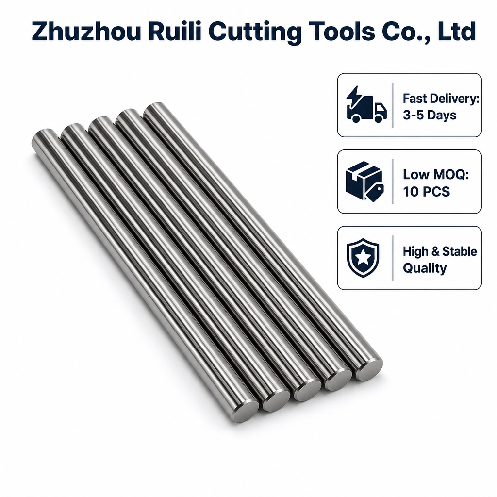
Full Article Structure
- 1. Introduction: Why Tolerance and Straightness Affect Finished‑Tool Quality
- 2. Dimensional Tolerance: Sintered vs Ground Solid Carbide Rods
- 3. Straightness Definition & How Rod Bend Creates Tool Run‑out
- 4. Specification Reference Table for OD Tolerance
- 5. Straightness Reference Values by Rod Length
- 6. Real‑World Tool‑Making Application Cases
- 7. Key Factors That Influence Final Rod Precision
- 8. Common Procurement & Specification‑Setting Mistakes
- 9. Quick Selection Table for Different Tool‑Blank Applications
- 10. Final Summary & Custom Precision‑Rod Support
1. Introduction: Why Tolerance and Straightness Affect Finished‑Tool Quality
Solid carbide rods serve as raw blanks for manufacturing end mills, twist drills and reamers. Many tool‑shop purchasers only specify nominal diameter and length when ordering carbide rods. They overlook two critical geometric parameters: outer‑diameter tolerance and straightness. Even with correct carbide grade and raw‑material quality, poor tolerance or excessive bending will cause multiple downstream troubles after tool grinding.
Out‑of‑spec diameter tolerance leads to clamping fit issues inside tool holders. Bad straightness creates residual bend inside the blank, which cannot be completely removed during grinding and results in finished‑tool run‑out. Excessive run‑out brings uneven cutting‑edge load, accelerated wear, vibration and poor workpiece surface finish. In serious cases, micro‑drills or small‑diameter tools will break during high‑speed machining.
This article explains solid carbide rod dimensional tolerance and straightness concepts, compares sintered and ground rod specifications, illustrates how straightness deviation impacts tool performance, shares real‑world production cases and points out typical specification‑setting errors. It offers practical reference for tool‑blank buyers, tool‑grinding workshops and cutting‑tool manufacturers.
2. Dimensional Tolerance: Sintered vs Ground Solid Carbide Rods
Tolerance represents the allowable deviation range for nominal outer diameter and length. Solid carbide rods are divided into sinter‑only (un‑ground) rods and precision ground rods, and their tolerance levels differ greatly.
Sinter‑only carbide rods come directly out of sintering furnaces without outer‑diameter grinding. They feature low cost but large dimensional scatter. Sintered blanks are suitable only for heavy stock‑removal secondary grinding or non‑precision static wear‑parts. They are not fit for direct use as cutting‑tool blanks.
Ground carbide rods go through diamond‑wheel outer‑diameter grinding after sintering. Manufacturers can achieve standard‑ground or high‑precision‑ground tolerance according to customer requirements. For rotary cutting‑tool blanks such as drills and end mills, ground rods are mandatory to guarantee clamping accuracy.
Note that diameter tolerance and length tolerance are independent parameters. Some buyers only write nominal size on RFQ without tolerance range, leaving all limits to supplier’s internal default standards, which easily causes dimensional mismatch after goods arrive. You should clearly define tolerance requirements on your inquiry or drawing documents.
3. Straightness Definition & How Rod Bend Creates Tool Run‑out
Straightness describes the axial bending amount along the whole carbide rod, usually expressed in mm per 100 mm length. Sintering internal stress will make long carbide rods produce slight bending. Short rods under 100 mm generally keep good straightness after standard production, while rods longer than 150 mm tend to have larger bend without dedicated straightening and fine‑grinding procedures.
Many people misunderstand that grinding can fully eliminate original rod bending. In fact, if the raw blank is bent, the grinder needs to remove uneven material allowance to get round outer surface. The central axis of the rod may still retain partial original bend. After you grind end‑mill or drill geometry on this bent blank, the finished‑tool central axis deviates, generating mechanical run‑out during high‑speed rotation.
Run‑out causes each cutting‑edge to take unequal chip load. Some edges wear fast while others barely cut. Vibration rises, workpiece surface quality degrades, and tool service‑life drops sharply. For micro‑size tools, small straightness error may directly lead to tool fracture.
4. Specification Reference Table for OD Tolerance
The table lists commonly‑seen outer‑diameter tolerance classes for solid carbide rods for tool‑making blanks.
| Rod Type | Tolerance Class | Diameter Deviation Range | Typical Application |
|---|---|---|---|
| Sintered (Unground) | General sinter tolerance | +0.3 ~ +0.7 mm | Wear‑part blanks, large‑stock secondary grinding |
| Ground OD | Standard ground tolerance | ‑0.010 ~ ‑0.030 mm | General‑purpose end mills, standard drill blanks |
| Ground OD | High‑precision ground tolerance | ‑0.003 ~ ‑0.010 mm | Micro‑drills, reamers, high‑precision finishing‑tool blanks |
5. Straightness Reference Values by Rod Length
Straightness requirement changes significantly according to rod total length. Below are industry‑common reference values for ground carbide‑tool blanks.
| Rod Length Range | Standard Straightness | High‑precision Straightness | Application Remarks |
|---|---|---|---|
| ≤ 100 mm | ≤0.05 mm / 100 mm | ≤0.02 mm / 100 mm | Most short‑length end‑mill blanks adopt standard straightness |
| 100‑200 mm | ≤0.08 mm / 100 mm | ≤0.03 mm / 100 mm | Long drill blanks recommend high‑precision straightness |
| > 200 mm | ≤0.12 mm / 100 mm | ≤0.05 mm / 100 mm | Must go through straightening process; cost rises for higher precision |
6. Real‑World Tool‑Making Application Cases
Two typical cases show how tolerance and straightness influence finished‑tool performance in actual tool‑manufacturing workshops.
Case 1: Long twist‑drill blank quality issue
A tool‑making factory purchased 180 mm length carbide drill blanks with only standard diameter tolerance specified, without clarifying straightness requirement. After external grinding and drill‑point machining, finished drills produced obvious run‑out during rotation test. Even diameter measurement was qualified, original rod bending caused axis offset. After switching to blanks with high‑precision straightness specification, run‑out problem was eliminated, and drill service‑life increased by 48 % in subsequent hole‑making production.
Case 2: Micro‑drill blank clamping deviation
An electronics‑tool workshop bought micro‑drill carbide rods with overly‑loose ground‑diameter tolerance. When installing blanks into precision collet chucks, inconsistent actual diameter caused unstable clamping. Some micro‑drills vibrated heavily and broke frequently. After updating RFQ document to require high‑precision ground tolerance, clamping repeatability got stable, and micro‑drill break‑down rate dropped greatly.
7. Key Factors That Influence Final Rod Precision
Multiple manufacturing links jointly determine final tolerance and straightness of finished carbide rods.
- Sintering process: Unreasonable sintering temperature curve and support fixture arrangement will introduce sinter‑stage bending for long rods.
- Straightening treatment: Long‑size carbide rods need dedicated straightening procedure before fine outer‑diameter grinding to reduce initial bend value.
- Grinding‑machine condition: Machine‑tool spindle accuracy, diamond‑wheel status and feeding parameter affect final ground‑rod geometric precision.
- Post‑grinding inspection: High‑precision batches require 100‑percent sampling measurement for straightness and diameter to screen out non‑conforming pieces.
Even good raw sintered blanks may lose precision if grinding equipment or inspection is insufficient. For high‑precision tool‑blank orders, you can ask suppliers to provide sampling inspection records of dimension and straightness.
8. Common Procurement & Specification‑Setting Mistakes
Many quality complaints originate from ambiguous specification requirements on purchasing documents.
First mistake: Only mark nominal diameter and length, without writing tolerance and straightness limits. Goods will follow supplier’s factory default standard which may not match your tool‑grinding requirements.
Second mistake: Assume outer‑diameter grinding will fully eliminate rod bending. Grinding corrects outer circle but cannot completely erase original axis bend for long blanks, so straightness must be explicitly requested.
Third mistake: Apply same straightness requirement for short rods and extra‑long rods. Longer rods naturally have higher difficulty to achieve ultra‑low bend value, unreasonable over‑strict requirement will raise unnecessary procurement cost.
Fourth mistake: Confuse sintered‑rod tolerance with ground‑rod tolerance. Sinter‑only blanks cannot be used as rotary cutting‑tool blanks even if you accept large tolerance range.
9. Quick Selection Table for Different Tool‑Blank Applications
Use this table to quickly match tolerance and straightness grade for your target tool‑blank.
| Target Tool‑Blank Usage | Suggested OD Tolerance | Suggested Straightness Grade | Important Note |
|---|---|---|---|
| Micro drill / precision reamer blank | High‑precision ground | High‑precision straightness | Strict control run‑out risk for tiny‑diameter tools |
| Standard short end‑mill blank (<100 mm) | Standard ground | Standard straightness | Suitable for most general‑purpose CNC end‑mill production |
| Long twist‑drill blank (100‑200 mm) | Standard / High‑precision ground | High‑precision straightness | Long blanks are sensitive to bending‑induced run‑out |
| Large‑stock secondary‑grinding blank | Sintered or standard ground | Standard straightness | Reserve enough grinding allowance to offset geometry deviation |
10. Final Summary & Custom Precision‑Rod Support
Dimensional tolerance controls outer‑diameter clamping fit, and straightness governs the bending status of carbide‑rod central axis. Sinter‑only rods and ground rods have huge precision gap. Straightness error of long carbide‑rod blanks will translate into finished‑tool run‑out, which worsens cutting performance and tool service‑life.
When preparing RFQ or drawing documents, clearly write diameter tolerance and straightness requirements according to rod length and finished‑tool type. Do not rely entirely on supplier default values. Distinguish sinter‑only blanks and ground blanks, and do not use sintered blanks for rotary cutting‑tool manufacturing.
If standard precision cannot satisfy your special tool‑making requirements, our factory can provide custom‑made solid carbide rods with special tolerance and high‑precision straightness according to your drawing parameters.
Precision Solid Carbide Rods & Custom Service
Custom‑Made High‑Precision Carbide Rods
OEM / ODM custom carbide rods: special diameter, non‑standard tolerance and extra high‑precision straightness for special‑tool‑blank projects.
CTA Contact Zone
Technical Consultation & Custom Orders
📧 Contact Us → /contact‑us.htm
Submit your rod dimension, target‑tool type, tolerance and straightness requirements. Get free specification advice and formal quotation.
Bulk Procurement & Global Distributor Partnership
📧 Contact Us → /contact‑us.htm
Wholesale pricing for bulk carbide‑rod orders. Support long‑term supply contracts with batch inspection documentation for cutting‑tool manufacturers and distributors.
Disclaimer
The information provided in this article is for general reference purposes only. Actual finished‑tool run‑out performance is also affected by grinding‑machine accuracy, collet‑chuck condition and grinding process. Please consult our technical team for application‑specific suggestions before large‑volume procurement of carbide‑tool blanks. All parameter data represents typical industry reference values under standard production conditions.