Precision Ground Carbide Strips Custom Machined to Your Drawings
- Share
- publisher
- Bree
- Issue Time
- Nov 10,2026
Summary
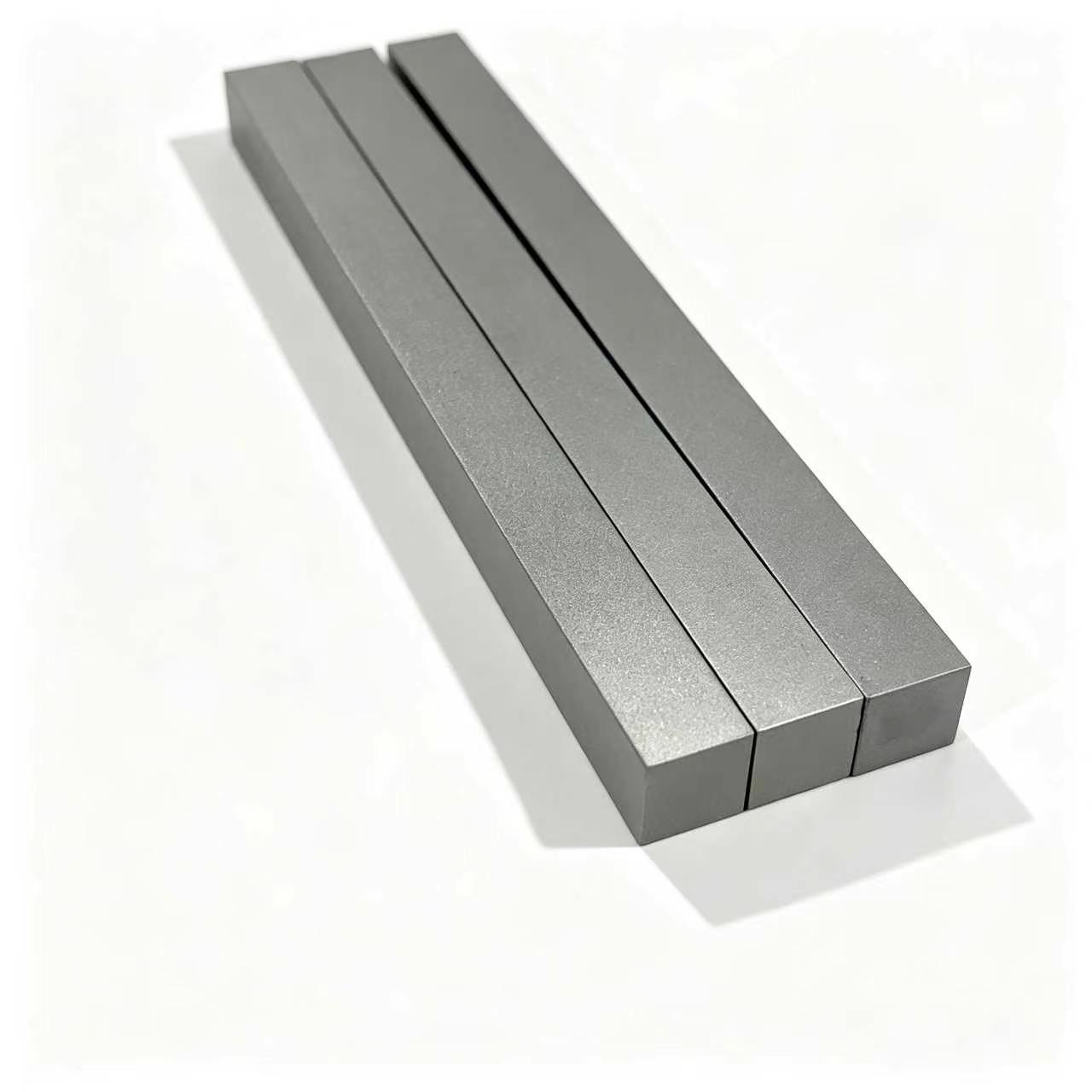
Precision ground carbide strips are bought as finished parts, so the drawing decides whether they fit. This article explains what a strip drawing must carry, how the dimension chain and functional tolerances are read before quotation, the grinding sequence from sintered blank to finished strip, available tolerance grades and surface finishes, the drawing errors that most often cause rework, and the inspection and packing steps used for ground strips.
Full Article Structure
- 1. Why Precision Grinding Decides Whether a Custom Strip Fits
- 2. Information a Strip Drawing Must Carry Before Grinding Starts
- 3. How a Drawing Is Read Before Quotation
- 4. Grinding Sequence From Sintered Blank to Finished Strip
- 5. Tolerance Grades and What Each One Costs
- 6. Surface Finish and Edge Treatment Options
- 7. Drawing Errors That Most Often Cause Rework
- 8. Inspection and Packing for Ground Strips
- 9. Summary
1. Why Precision Grinding Decides Whether a Custom Strip Fits
A precision ground carbide strip is not a blank. It is a finished part, and it is judged by fit. In a sealing slot, a blade holder or a wear plate groove, a deviation of a few hundredths of a millimetre changes the result: the strip either slides in with a controlled gap or it binds, chips at the edge and fails early.
Because cemented carbide cannot be corrected by ordinary machining after sintering, every dimension must be settled on the drawing before grinding begins. Diamond grinding removes material slowly and at real cost, so an unclear drawing is not a communication inconvenience. It is a direct source of scrap.
This article explains what a strip drawing needs to contain, how the drawing is read before quotation, how grinding proceeds stage by stage, which tolerance grades are realistic and which drawing errors cause most rework. The aim is to let you confirm everything on paper first, so the parts arrive matching what your assembly expects.
2. Information a Strip Drawing Must Carry Before Grinding Starts
A strip order can only be quoted accurately when the drawing answers the questions below. Items in the first table are required; items in the second improve the result but are not strictly necessary.
| Required Item | Why It Matters |
|---|---|
| Length, width and thickness with tolerance per dimension | Defines the grinding allowance and the inspection plan |
| Datum face and measuring method | Two suppliers using different datums produce parts that do not interchange |
| Edge form: sharp, chamfer or radius, with size | Edge preparation is a separate grinding step and affects cracking risk |
| Carbide grade or required hardness | Determines sintering recipe and grindability |
| Working condition and load type | Drives grade recommendation when the grade is not fixed |
| Quantity and whether a sample is required | Sets batch planning and whether a first-off approval is scheduled |
| Helpful Item | Effect on the Result |
|---|---|
| Surface roughness requirement (Ra) | Avoids over-grinding cost or under-grinding friction problems |
| Assembly drawing or a photo of the installed position | Shows which dimensions are functional and which are free |
| Flatness, straightness or parallelism limits | Prevents a part that measures correctly but rocks in the fixture |
| Magnet or corrosion requirement | Points to a nickel-bonded or chromium carbide grade |
A sketch with dimensions and no tolerances can support a preliminary price, but not production. If you only have a sample part, send the sample dimensions with an indication of which faces are functional; the drawing can be confirmed from there.
3. How a Drawing Is Read Before Quotation
Before a strip is priced, the drawing is checked in a fixed order. This step prevents most later disputes.
3.1 Separate functional dimensions from free dimensions
Only a minority of dimensions on a strip usually matter: the thickness that sets the gap, the width that enters the slot, the length that reaches the mounting point. Tightening a free dimension adds grinding time without improving function, so the first question is always which dimensions carry the fit.
3.2 Check the dimension chain for accumulation
Strips are often dimensioned from both ends or from an intermediate step. If several tolerances stack along one direction, the total variation at the last feature can exceed what the assembly allows even though each individual tolerance looks reasonable. In that case a cumulative limit or a single reference datum is proposed.
3.3 Confirm units and edge notation
Inch and millimetre values are frequently mixed in drawings transferred between engineering teams. Chamfers are also written in two different ways: a C-value notation describes the leg length, while an axial chamfer length describes the distance along the edge after a 45 degree cut. The two are not the same number. Converting silently is how an edge ends up visibly different from the drawing, so the notation is confirmed in writing.
3.4 Verify feasibility against thickness and slenderness
A tolerance that is routine on a 10mm bar is not routine on a 1.5mm thin strip. Thin sections deflect during clamping and grinding, and very slender strips are sensitive to cracking at sharp edges. When the requested tolerance is beyond what the section can hold, a realistic value is proposed together with the reason.
4. Grinding Sequence From Sintered Blank to Finished Strip
A ground strip passes through a fixed sequence. Each stage has its own purpose, and skipping one usually shows up as a defect later.
| Stage | What Happens | Typical Effect |
|---|---|---|
| Blank preparation | Sintered blank sorted by size, allowance checked | Ensures enough material remains for all grinding passes |
| Rough grinding | Both large faces ground flat, stock removed in steps | Establishes the thickness reference and relieves surface distortion |
| Four-side grinding | Length and width brought to size with the datum face held | Builds the final section |
| Edge and profile work | Chamfer, radius, groove or bevel ground | Defines edge strength and the cutting or sliding contact |
| Finish grinding | Final passes at reduced depth of cut for tolerance and finish | Reaches the specified tolerance band and roughness |
| Inspection | Dimensions, flatness and appearance checked against the drawing | Confirms acceptance before packing |
Fine grain grades grind to a better finish but take more passes; high cobalt grades are tougher and slightly more forgiving at the edge. This is why the grade and the tolerance band are quoted together, not separately.
5. Tolerance Grades and What Each One Costs
The bands below are the working reference used for strip quotations. They are achievable ranges, not a promise independent of part shape, and the final value is fixed on the confirmed drawing.
| Grade | Typical Band | Best Suited To | Cost Effect |
|---|---|---|---|
| Commercial | about ±0.05 mm | Wear plates, liners, general sliding parts | Lowest grinding cost |
| Precision | about ±0.02 mm | Blade holders, guide strips, sealing slots | Standard for most OEM orders |
| High precision | about ±0.01 mm | Mating pairs, interchangeable assemblies | Slower passes, higher inspection share |
| Ultra precision | about ±0.005 mm or tighter | Metrology, precision sealing, special tooling | Requires stable fixtures, longer lead time |
Two factors move a part between grades in practice. The first is section thickness: a thin strip is harder to hold than a thick bar at the same tolerance. The second is aspect ratio: a long narrow strip tends to bow, so straightness rather than size may become the limiting requirement.
6. Surface Finish and Edge Treatment Options
Finish and edge form are usually the difference between a strip that performs and one that wears a counterpart part.
- As-sintered: no grinding, loose dimensions and a rougher surface; acceptable only for non-critical liners;
- Rough ground: dimensionally usable, visible grinding pattern, moderate friction;
- Fine ground: Ra around 0.4 to 0.8, the common choice for sliding and sealing faces;
- Polished: Ra around 0.2 or better, used where friction, pickup or appearance matters;
- Edge options: sharp edge for cutting, chamfer for crack resistance and safe handling, radius for sliding contact against a soft counterface.
For strips that will be brazed or clamped, a controlled chamfer also protects the joint from edge chipping during assembly. For strips used as cutting edges, the bevel angle and land width are specified instead, because they set the load on the edge.
7. Drawing Errors That Most Often Cause Rework
- No datum face, so two grinding runs measure differently and parts do not interchange;
- A tolerance carried over from a steel drawing that a thin carbide section cannot physically hold;
- Chamfer given as an axial length in one place and as a C-value in another;
- Mixed inch and millimetre dimensions with no unit note;
- Surface described only as polished, with no roughness value, so acceptance is subjective;
- Edge form left open, then judged on arrival;
- Holes, grooves or bevels added after production has started, which reopens the grinding plan.
All of these are cheap to resolve in a drawing review and expensive to resolve after grinding. A written confirmation of the interpretation before the first pass removes almost all of them.
8. Inspection and Packing for Ground Strips
Ground strips are inspected against the confirmed drawing, at the points that carry the fit.
- Thickness measured at several positions along the strip, not only at one end;
- Width and length checked with a micrometer or height gauge on the stated datum;
- Edge form and chamfer checked visually and by comparator where the size is small;
- Flatness and straightness checked on a surface plate for long or thin strips;
- Surface roughness verified with a roughness tester when a value is specified;
- Appearance checked for cracks, chipping and grinding marks before packing;
- Each piece separated by foam, thin strips stacked flat, long bars in a rigid case to avoid bending in transit.
Inspection records are kept per batch so a later question about a delivered lot can be answered from documents rather than from memory.
9. Summary
Precision ground carbide strips are a drawing-driven product. The grade fixes the material behaviour, the grinding sequence fixes the geometry, and the drawing fixes whether the two meet. Confirm the datum, the functional dimensions, the edge notation and the tolerance band in writing before the first pass, and keep the same documents for repeat batches so the second order matches the first.
If a requested tolerance looks unusual for the section, ask for the reason instead of accepting it silently. Usually the requirement can be met with a small change in how the part is dimensioned, and that conversation costs far less than a rejected lot.
Related Products
Related Articles
Send your strip drawing with the required grade, tolerance and quantity. The drawing is reviewed for datum, edge notation and feasibility before a formal quotation is issued.
Contact Us For Drawing Review →Tolerance and finish values in this article are reference ranges. The final specification follows the confirmed drawing and order agreement.